3D Printed Curta Part V
- Marcus Wu
- 3 dprinting , Curta
- July 11, 2015
Tolerances in OnShape
I waited through two updates to OnShape and decided that I needed to stop waiting on them for features. I used their version control to set up a branch for my tolerance work and then used expressions to add in the tolerances I calculated based on my previous tests on my printer and the tolerances specified in the Curta engineering drawings. This allowed me to begin printing and I can go back and update these expressions to used shared dimensions later when they are added.
Initial Printing
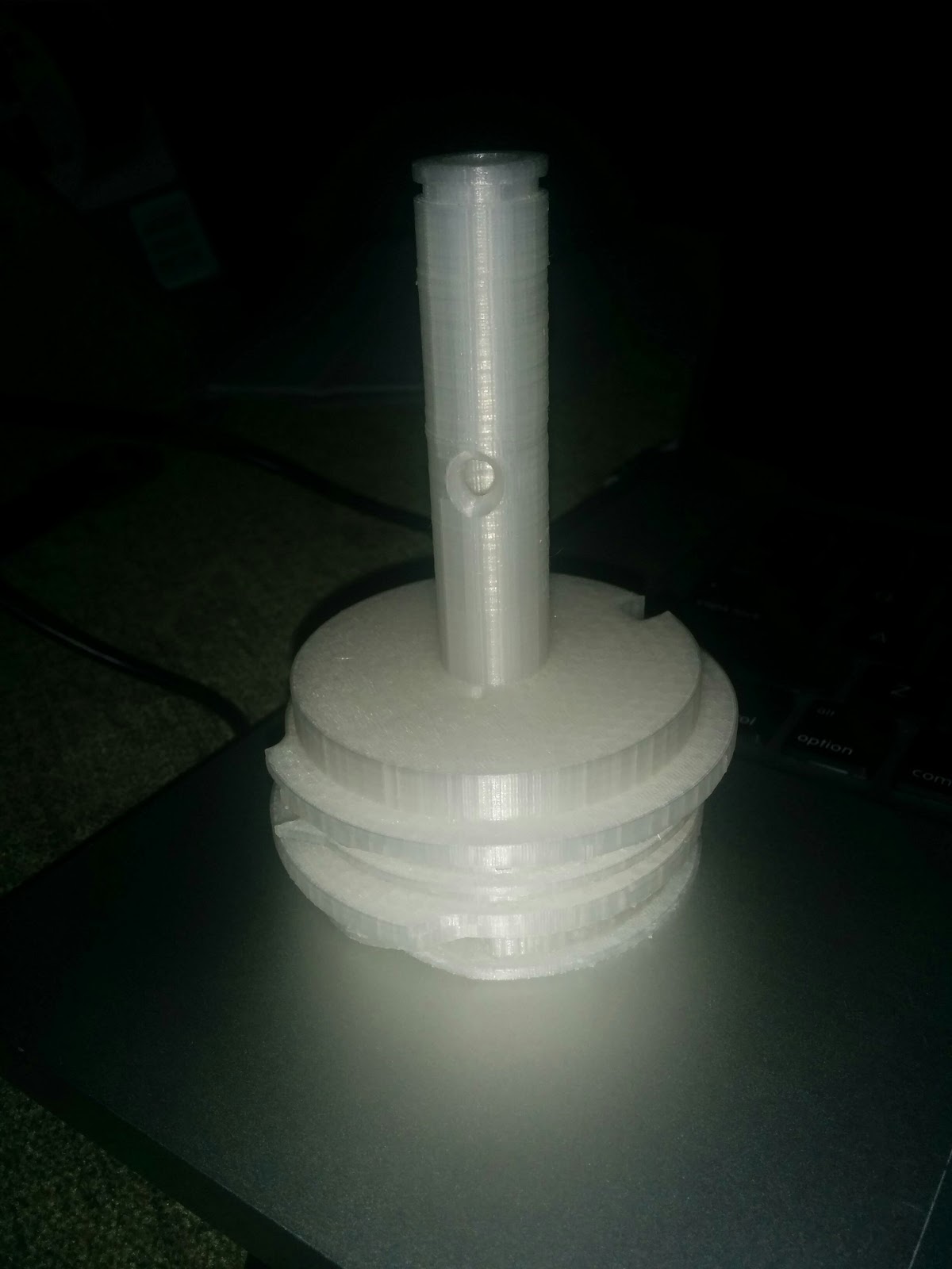
I started my first prints at 3:1 scale. I printed a section of transmission axle, a sleeve for the ratchet gears, a selector shaft, and selector knob. The initial versions of the transmission axle and sleeve did not fit well due to a mistake in the models, but that was easily fixed. Support material was needed for the selector knob. I think it turned out well. I also printed a tens bell and a c-clip for it and they turned out mostly well, but another modeling mistake meant that the rings on the tens bell were misaligned. The bottom ring also warped during printing so it will need to be reprinted. I have altered the model to align the rings properly and increase the footprint in contact with the print bed so that warping issues will be reduced.
I searched around and found some steel balls at the right size for the selector knob and shaft. It turns out that the right size matches #TT steel shot. I couldn’t find it in any smaller quantity than a 10lb bag, though. When I got those delivered I improvised a ball point pen spring to assemble the selector shaft and knob. I am very happy with how that turned out. See the pictures and video below.
I look forward to further printing and getting more parts of the Curta assembled.
Descriptions of the gallery photos below in order:
- Misaligned tens bell. I will be reprinting it soon.
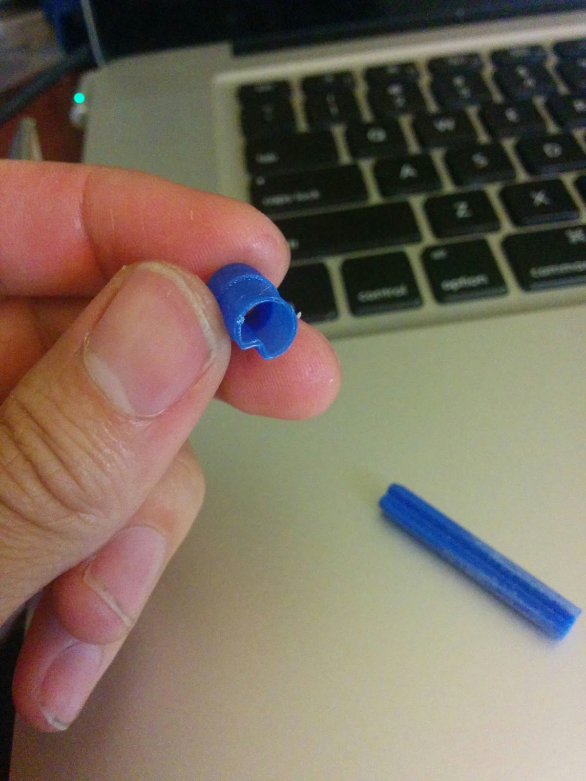
- Transmission sleeve and shaft section
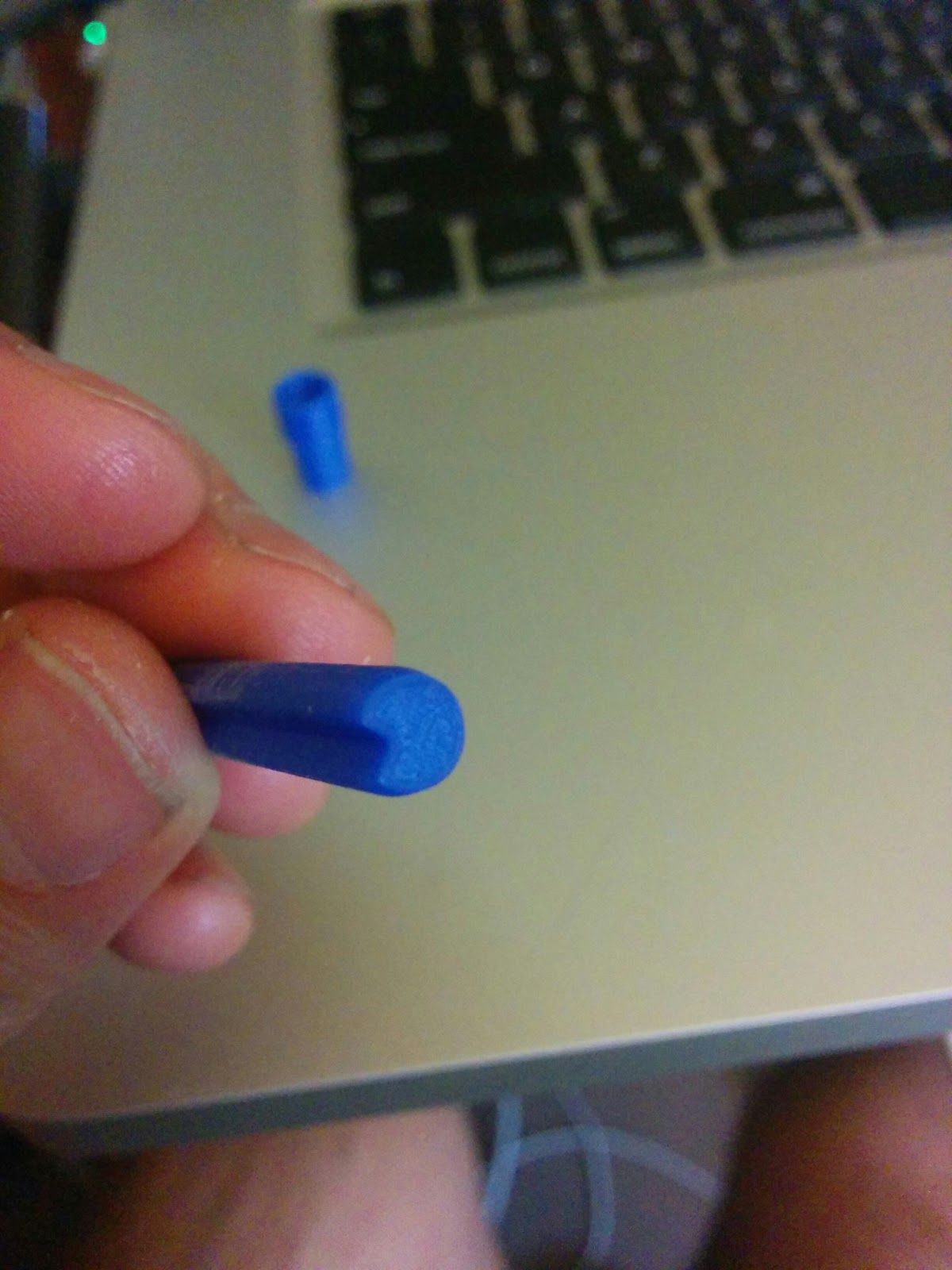
- Close-up of the profile of the transmission shaft
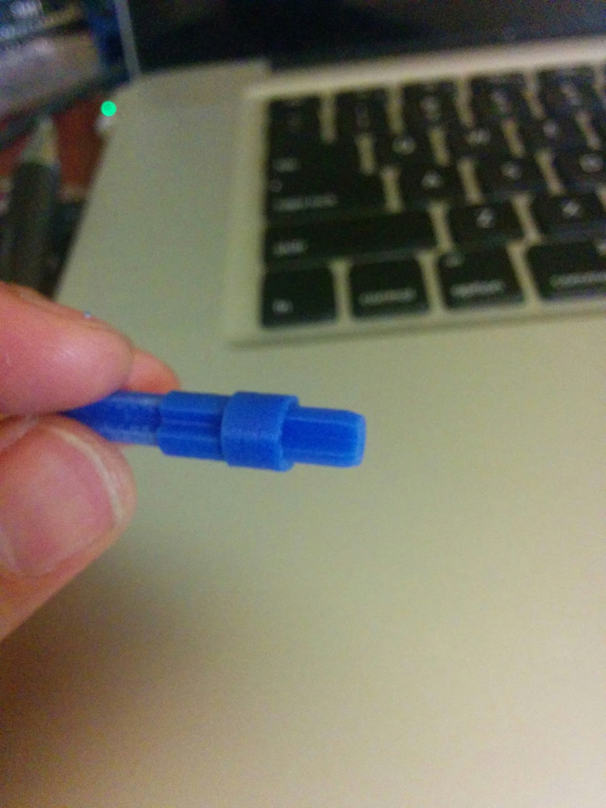
- Transmission sleeve on the transmission shaft. It slides smoothly as it should
- This is the #TT steel shot I used for a ball bearing in the selector shaft / knob assembly.
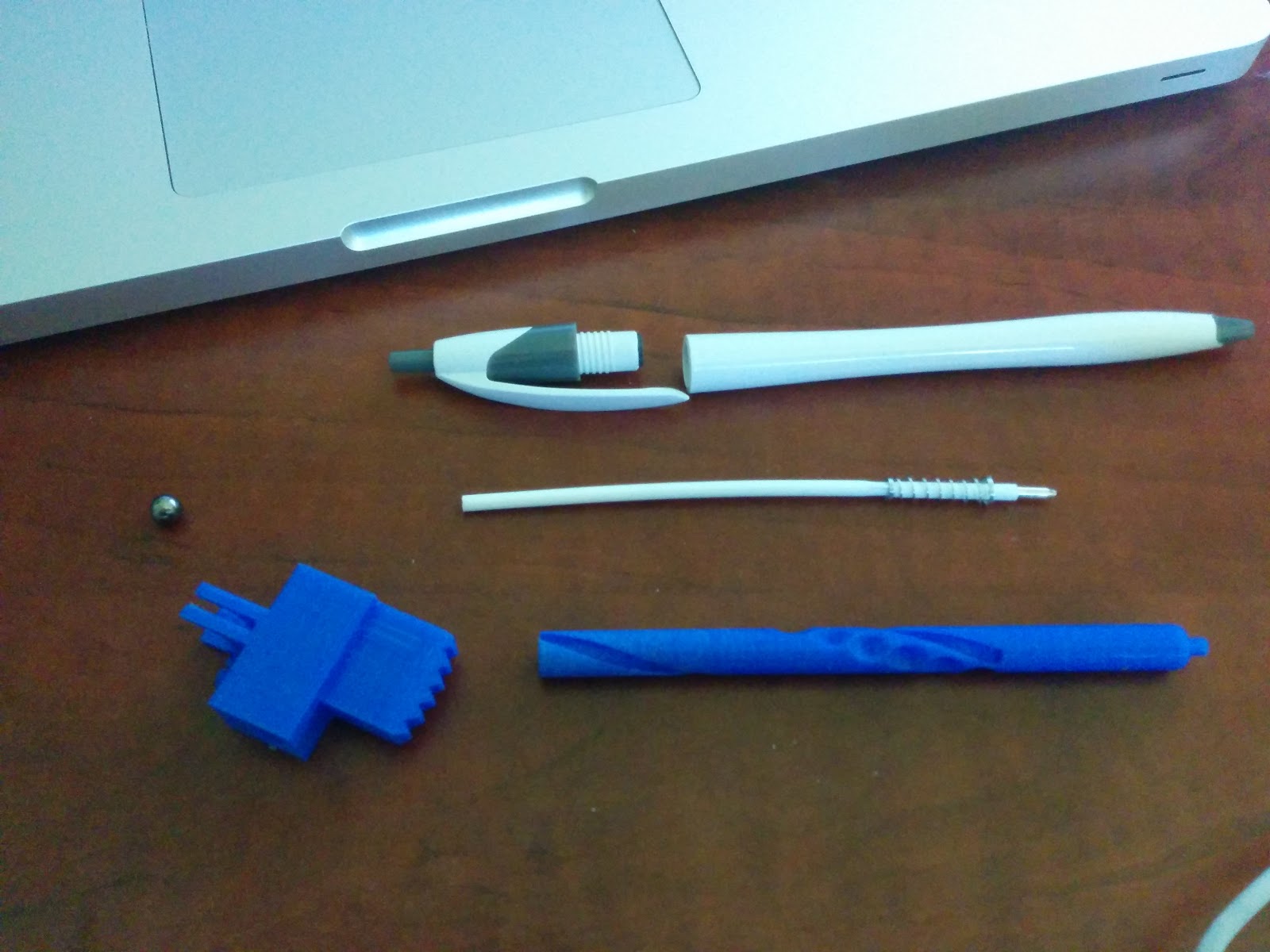
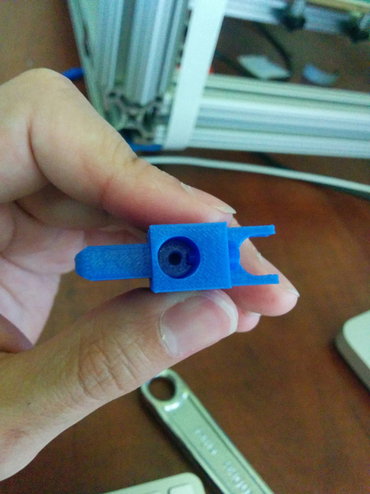
- The selector shaft, knob, steel ball, and the ball point pen disassembled for its spring.
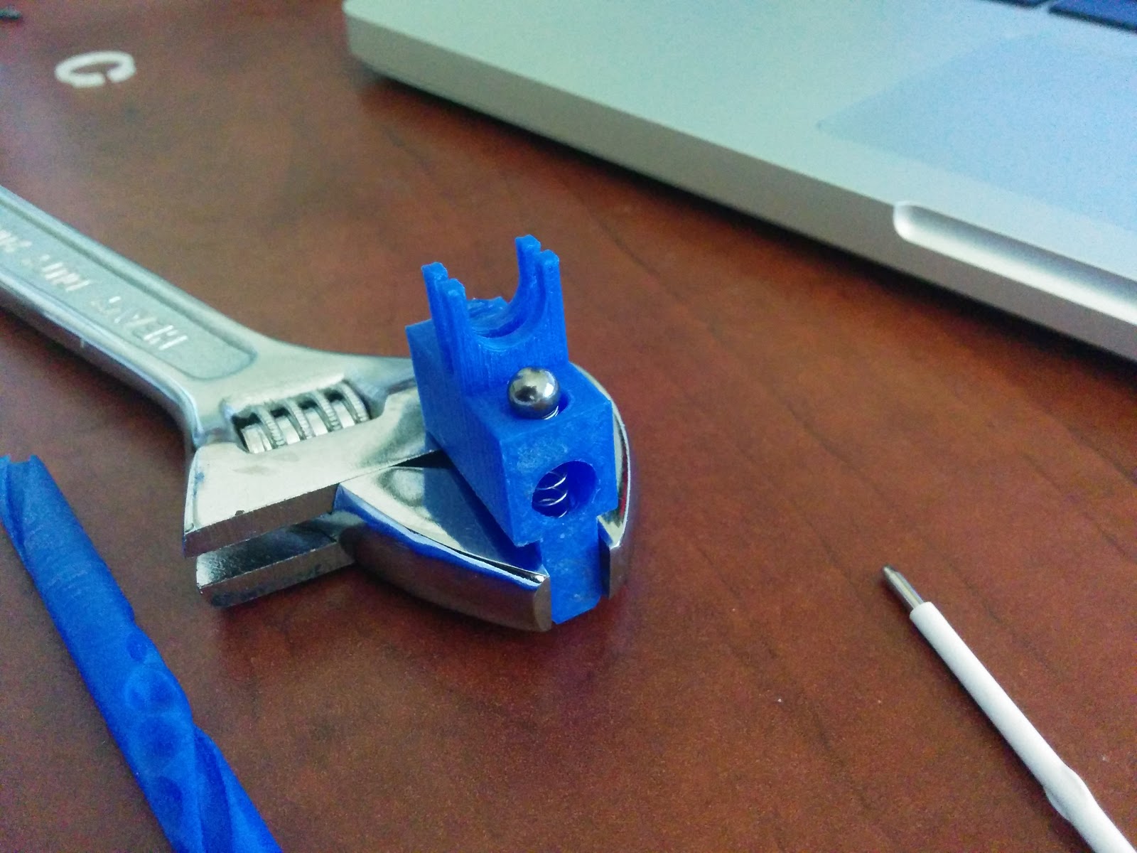
- The selector knob with the spring and steel ball. The adjustable wrench is not tight and is there only to keep the knob upright.
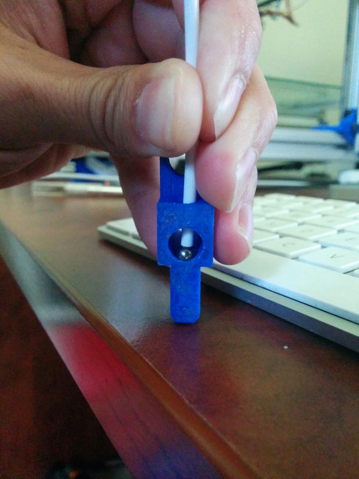
- In order to press the ball and spring down without the ball shooting out and taking an eye out, I placed my thumb on the short side while sliding the shaft in the opposite side (the wrong way) to limit the ball and spring’s movement.
- Here is the steel ball and spring pressed into place. The tube I am using to press the ball bearing and spring down with is the ink tube from the ball point pen.
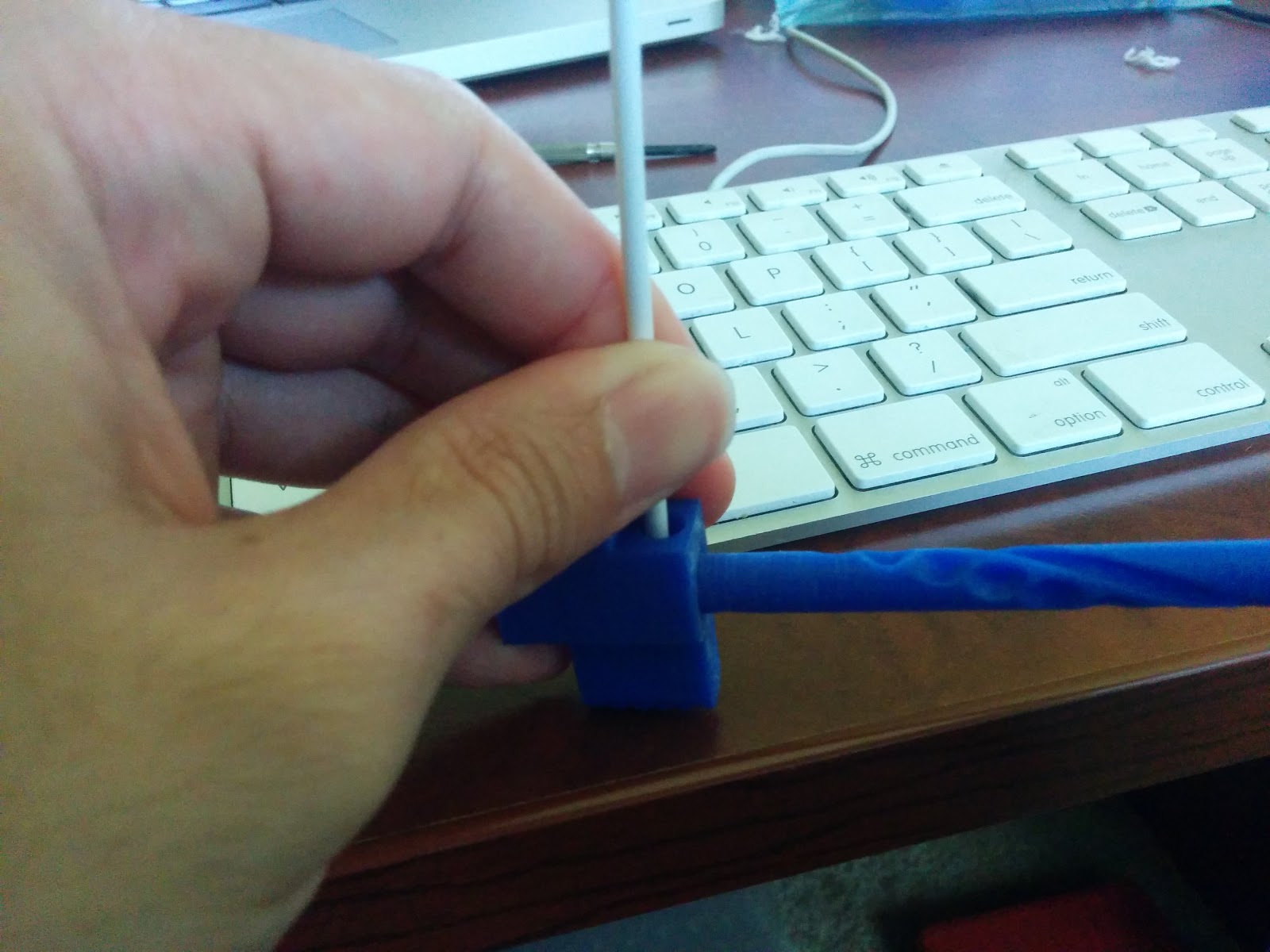
- Now that the steel ball and spring are pressed into place, the shaft can be slid into the knob in the correct orientation. Once the shaft is covering the ball bearing as far as it can, pressure on the ball bearing and spring no longer needs to be maintained.
- As the selector knob is slid onto the shaft, the guide screw will need to mate to the slot in the selector shaft.