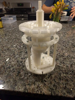
3D Printed Curta Part VII
- Marcus Wu
- 3 dprinting , Curta
- February 29, 2016
Much more printing
I have done a lot more printing since I posted last.
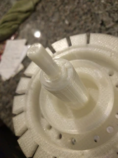
Step Drum and upper portion of the main axle
The main axle is just a little bit taller than I can print. I might have been able to modify my printer a little bit to print that tall, but the print bed on my printer is the y-axis so the parts move back and forth as I print. That could cause a tall print to dislodge from the print bed. Instead I divided the main axle into two keyed parts. It is divided such that the parts mate inside the middle of the step drum. The upper part I combined with the step drum and printed as one piece. The lower piece will slide into the bottom of the step drum with a tight fit – no glue necessary.
I also could have tried printing the main axle horizontally, but the z-axis resolution is limited by the layer height you specify. I might have been able to get a pretty round axle, but the first layer is often slightly squished when printing (it takes a lot of time to tune a printer to be 100% perfect on the first layer and the tuning must be repeated often) and the footprint area that the first layer adheres to the print bed would be very small which also could lead to the print dislodging from the print bed.
After printing the step drum and main axle I found that I had a mistake in my models. The step drum teeth were misaligned by 20 degrees. I had to fix the model and reprint. That was a painful mistake as it took 13 hours for each print.
Main axle bottom portion
Since I split the main axle, I needed to print the bottom part separately. The keying of the two parts is important. The bottom portion of the axle must be oriented properly and the key ensures that it is. After having printed it and carefully fitting it into the step drum, I had a completed main axle. Only I discovered later that the engineering drawings are either incorrect or from different versions of the Curta Type 1. The orientation of the lower portion of the main axle was 90 degrees off. That was easily fixed by altering the direction of the key I added after dividing the main axle into two parts.
Other printing
- bearing plate
- anti-reversal plate, zero positioning lever, and anti-reversal lever
- body support columns
- some of the transmission axles and gears
Making springs
To make the zero positioning and anti-reversal mechanisms work, I needed to make a couple of springs. All other things kept the same, a torsion spring scales up the force it exerts with the diameter of the wire used to make the spring. That made things easy for me – I simply multiplied the wire diameter from the original engineering drawings by three for my 3:1 scale Curta.
In order to make springs, you need to have the right kind of metal tempered the right way to make it springier than it is malleable. To this end I got some music wire from a local hobby shop. To actually form the spring, I printed out a couple of mandrels – basically cylinders with a hexagonal end that I could fit into the chuck of my drill. I made the mandrels a little bit smaller than I needed the springs to be because the wire will want to relax after winding.
Warning
This can be very dangerous, so take all of the necessary precautions if you try this (eye protection, gloves, thick clothing, etc)!
I placed the wire and mandrel into the drill so that the chuck grabbed both and very slowly turned the drill while using pliers to hold the wire taught at a tangent to the mandrel. My drill chuck would not turn without the drill turning. Ideally I would have turned it by hand. As the mandrel turns, it will begin wrapping the wire. Keep the loops tight together (it may take some practice to get this right). Once I had the number of loops required, I put the drill in reverse and slowly let the springy wire unwind as much as it wanted to.
It’s very important to do let the wire unwind slowly. If the wire is released too early, it will violently unwind while whipping around and possibly causing injury. I accidentally had this happen to myself while winding the thicker wire. When the spring unwound it whipped into my hand. The force broke the skin and left a nasty bruise. I thought for a moment I might have broken it. I’ve broken a finger before and it actually hurt less than that wire.
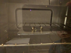
Once I had wound my springs, I put them into a toaster oven for as hot as it’d go (450-500 degrees Fahrenheit) for 30 minutes and let them cool slowly inside the oven without opening it. That helped temper the wire so it would keep its shape.
Making thread
Many of the parts on the Curta have either external or internal thread so that they can receive screws or nuts. There are some shoulder bolts I couldn’t find as well so I set out to cut thread into 3D printed parts using a metric tap and die set I have.
After several tries, I gave up on the 3D printed shoulder bolts. They were M5 bolts and I printed them head down on the print bed so I wouldn’t need supports, but that meant that the layers aligned normal to the length of the bolt. The weakest part of a 3D print is between the layers, so as I tried to thread the bolts, they sheered off leaving plastic bits in the die I was using. I eventually decided I could produce those bolts by printing a sheath for a normal M5 bolt to create a shoulder at the size I needed.
After solving that issue I still needed some external thread. The support columns are threaded at the ends so they can be connected to the body and the bearing plate of the Curta using hex nuts. I tried a lot of different methods, but what worked in the end was printing the support columns horizontally to change the layer alignment and prevent the part from shearing as I threaded it. I used a combination of raft and brim to prevent them from coming loose off of the print bed. They aren’t perfectly round, but it doesn’t matter much for those.
Cutting internal thread was not nearly as difficult. I was able to just turn the die into the plastic a quarter turn at a time. After each quarter turn I would reverse direction to help clear out some of the excess plastic. Depending on how good the first cut was, sometimes I would put the tap through a second time (being very careful not to cross thread it)
Descriptions of the gallery photos below in order:
- The springs I wound in the toaster oven getting tempered
- The top of the main shaft with the washer and printed circlip connecting the Curta body and tens bell together.
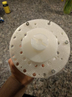
- The bottom of the Curta showing the bearing plate and zero positioning / anti-reversal plate. The nuts at the bottoms of the support columns are also visible.
- The Curta looking top-down.
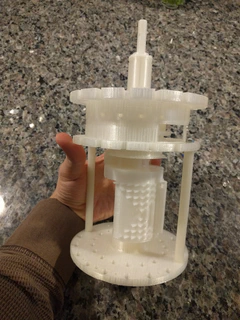
- A side view of the Curta with the step drum visible.
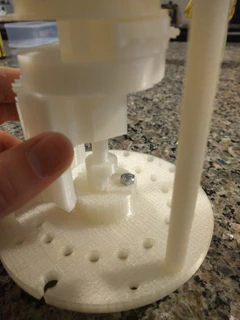
- The anti-turn plate bolted into the bearing plate – an observant eye will notice that this picture was taken before I fixed and reprinted the lower part of the main axle.
- Ready for some transmission axles next
