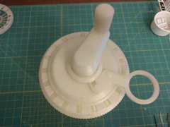
3D Printed Curta Part IX
- Marcus Wu
- 3 dprinting , Curta
- August 29, 2016
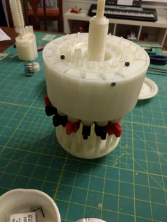
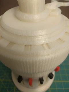
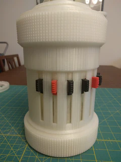
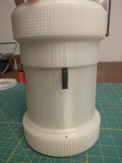
Completing Assembly of My 3D Printed Curta
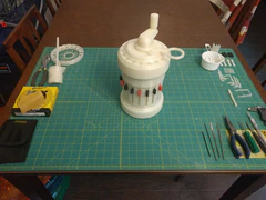
I applied for and received an invitation to the Charlotte Mini Maker Faire ! I look forward to seeing readers of my blog and other makers there! If you’re in the area, please stop by and tell me you’ve seen my work online.
After having completed the main portion of the Curta, I started to focus on the upper carriage portion. At first I thought this would be a breeze as it is mostly the digit dials which spin on axles connected to the carriage casting. I encountered multiple issues which I will detail below.
Digit Axles
The digit axles were one of the easier prints out of the carriage assembly, but I did end up increasing the infill because the axles broke off in the carriage casting a few times when I put too much pressure on them. The main time this happens is when screwing the carriage ring onto the carriage cage.
I printed these with the wider section down on the print bed with a small amount of support because they have a cutout that helps them sit in the carriage cage. I ran them through a rough sanding to smooth them out some and then sprayed them with the PTFE lubricant I have been using.
Digit Dials
The digit dials were pretty straight forward and almost as easy as the digit axles. They did require support for the geared portions. I printed them with the numbered dial downwards and the geared portions facing upwards. There were two types, some with a one-piece geared segment and some where it was two pieces. This is so that the teeth on the clearing ring don’t interfere with normal operation of the Curta while the clearing ring is in one of its resting positions.
The only issue I had was that the hole for the pins that depress the carry levers were so close to the edge of the dial that it caused the outside diameter of the dials to not quite be a complete cylinder. I also sprayed these with the PTFE lubricant. I tried to keep the lubricant on the inside of the shaft only.
Carry Pins
The carry pins exert pressure on the carry levers and I didn’t want to have problems with them breaking off so instead of printing these vertically, I printed them horizontally. Due to their small size and their function, I printed them at 100% infill. I printed most of the carriage parts at 0.1mm layer height, but I took special care to print these at that layer height so they were rounder when printed horizontally. A small bit of filing was necessary to fit these. I estimated the distance to insert them into the digit dials and then later fine tuned it when the dials were placed onto their axles and seated into the carriage cage.
Clearing Disc
The clearing disc was interesting. I printed it upright which meant lots of support underneath it, but I wanted to keep the top surface clean. The difficulty is in the groove for the decimal markers. The Simplify3D support didn’t work as well printed on a slanted surface.
I printed this with 30% infill at 0.1mm layer height because it is an outside facing part. I want the sanding and filling to be easier later prior to painting.
Carriage Casting
The carriage casting was a real trick to print. This one had me stuck for about two months. It wasn’t terribly difficult to get the initial print done: I printed it upside down to avoid support material. The problem was once I added in the digit axles and digit dials, it didn’t align properly with the lower portion of the Curta. The digits would seat onto the transmission shaft crown gears, but they would not align with the carry levers properly. The alignment problem was also obvious from the spider spring whose fingers did not perfectly match up to the holes on the top of the casting.
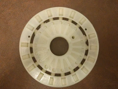
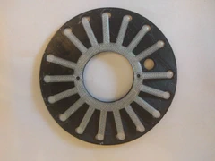
I checked my printer, my models, and even the slicer (by trying another slicer). I also put in a support ticket with Simplify3D to see if they could find a problem with what I was doing or with the software itself. They were very helpful, but couldn’t point me towards a definite cause.
Finally, I flipped the model over and printed it with the support I was avoiding. Something about the rotation re-aligned the ball bearing holes and digit axles to the rest of the Curta and to the spider spring. At first I thought rotating the model to eliminate support material caused some rounding error in the model, but after reviewing the CAD I realized that I had designed the part in the same orientation I originally printed it (there was no rotation for the original print). If anything, it seems like any rounding error encountered when rotating the part upside down should have thrown the reprint off further.
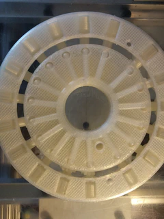
At this point I’m not 100% sure why flipping the part over helped, but I’m glad I discovered the workaround.
Carriage Cage
The carriage cage had the same issue as the carriage casting as far as alignment goes. It also had the same solution. However alignment wasn’t the only issue I had with the carriage cage. The engineering drawing was somewhat difficult to interpret so it took a few iterations to get the right output. The threading on its lower outer edge where the carriage ring connects also required an extra iteration. The carriage ring didn’t thread on nicely at first and I had to decrease the diameter of the threads about 0.2mm before it would.
I printed the carriage cage at 30% infill with a 0.1mm layer height. The original print required no support, but the reprint to correct the alignment issues required a lot of support.
Carry Levers
After getting the carriage assembly mostly complete I connected it up to the lower portion of the Curta to try out some simple carry operations and found that the carry pins on the number dials now met the carry levers, but did not press the levers enough to trigger them.
Initially I worked on fine tuning the carry levers to smooth out their action and improve their positioning. I was able to get many of the levers to carry properly, but there was a very small window of alignment where they would both trigger a carry and reset afterwards. For some of them the window was so small that simply triggering a carry and reset would push it out of position far enough to not work (this was on the order of 0.1mm or less). Another fault I encountered was that sometimes the tens bell would not push the lever high enough to prevent friction from causing an errant carry during the next operation.
When I realized just how finicky they were, I went back into CAD and altered the levers to be just a little bit taller. This way the levers would trigger more easily and could be adjusted a little bit lower so that the tens bell could engage them more completely to reset their original positions. That change helped significantly, but I had to adjust the length of the levers more than once before I found the sweet spot in size. If the lever is too tall it can interfere with the number dial’s ability to turn during the carry operation (and potentially break something – like the main shaft).
I think I printed each lever about three times. They were printed at 100% infill in a vertical orientation. Each one (there are 15) had their sides and edges filed to smooth them out. The final round of recalibrating the levers went significantly easier because with a better height, they were less finicky about their position. I did find I had to adjust the bends in the carry lever springs after extending their height.
Breaking the Main Shaft … Again
I broke the pin next to the main shaft (which drives the tens bell) while testing the carry levers. I reprinted the main shaft, but during the long print I decided to experiment with using resin to repair and strengthen the part. I mixed some resin and hardener and poured some into the hole where the pin broke off. I then poured some more resin into the pin itself at the break point. Since printed PLA isn’t water-tight, the resin seeped throughout the part. Using a piece of toothpick to hold the parts together, I let it cure.
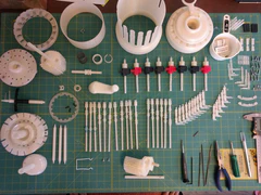
I believe the main shaft got stressed when the tens bell pin broke off. Shortly after repairing the tens bell pin, the main shaft broke during normal operation. I tried swapping the tens bell out for the one I printed when the tens bell pin broke, but I had accidentally printed an old copy which had its teeth misaligned (see Part VII ). Instead I repaired the main shaft in the same way I repaired the tens bell pin. When I get more filament I will reprint with the correct model.
As with last time, I will print the main shaft portion of the model with 100% infill, but this time I will also extend that solid infill to the top few layers of the step drum.
Other parts
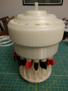
I also printed the spider spring and spacer parts, clearing cover, clearing ring, clearing plate plunger, clearing tooth racks, the rivets for the clearing ring, the main bearing sleeve, the collar, the carriage ring (the knurled part you grip), and the lower housing. These parts all printed pretty easily and assembled easily. For the most part I stuck to 0.1mm layer heights and 30% infill. The plunger was printed at 100% infill and printed horizontally for strength. It required some filing / sanding to round it out some.
Curta Function
The Curta now functions well. I have been able to run different operations, but I haven’t been able to do much actual math without numbers on the results dials. I plan on printing some temporary paper wraps for them soon so I can record some videos on it.
The carriage does lift and rotate to allow multiplication and division by tens. The clearing ring rotates, but I have noticed that it is tough to turn and doesn’t always leave every digit on zero. I’ll have to work on tuning that. Subtraction seems to work beautifully, but with more friction than addition. The reversing lever works nicely as well.
Two printed parts just weren’t living up to their intended functionaly. These were the spider spring and the stepped drum positioning spring (it connects to the bottom of the tens bell). I figured I might have some trouble with those parts so I had already been working on a plan to beef them up to improve their springiness in plastic.
For the stepped drum positioning spring, I thickened up the arms and added a half-cylinder to each leg to increase rigidity. That did the trick quite nicely – the step drum now pops up and down between the addition and subtraction positions. I reprinted this the same as the original at 100% infill on its side with support material.
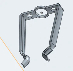
For the spider spring, it has a couple of washers that sit over it. I combined those with the spider spring to increase its thickness and tapered off the fingers to the original height. That stiffened up the design, but I also decided to increase the infill from 30% to 50% with the intention to increase it further should I continue to have issues. So far it seems to be working quite well. We’ll see how it does over time.

So far these are the only two parts I have redesigned. I have combined parts and divided parts in order to get prints to work more easily, but these two parts have actually changed form slightly due to the attributes of the material and manufacturing process.
Video
Update: Here is a short video demonstrating a simple add and subtract 2
Curta Logo work
While I was doing all that work (particularly in the two month period I was stuck on the carriage casting alignment issue), I got a head start on the numbering and lettering on the Curta. I searched quite a bit and couldn’t find a font which matched the text on the Curta exactly.
I ended up deciding to use OnShape to actually CAD the text. I worked from the engineering drawings which had some dimensions, but not all of them (the curves in particular were missing dimensions).
When I was done, I wanted to know just how close I came to the engineering drawings I was working from so I exported the CAD sketch as a .dwg file. I used a section of the engineering drawing and the exported sketch to create an overlay. The CAD sketch was only scaled (uniformly) and positioned. Neither the letter spacing nor the aspect ratio were altered. Below are the results which came out pretty darn close.


Next Up – Paint
I plan on painting the Curta – it isn’t very functional without being able to see the math being done. Most of the parts needing painting are external parts where changes in dimensions don’t matter, so I have that going for me. However I also have moving parts and parts that will need quality lettering and numbering. My current plan is to use a laser cutter to cut masks out of masking tape for the lettering. I don’t know what type of paint to choose either.
What's that you say? A 3d printed Curta computer can't be built? Wrong! https://t.co/S0CmhCgHCU
— Adam Savage (@donttrythis) May 12, 2016
Incredible dedication.
The attention this project has gotten is flattering!
More Curta pictures
Descriptions of the gallery photos below in order:
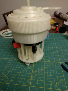
- Nearly ready to fully assemble.
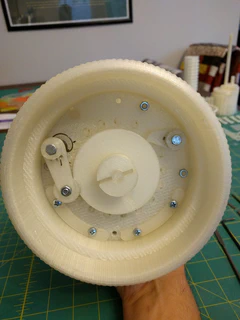
- Bottom of the Curta (minus the base plate) after assembly.
- Curta minus the lower housing and crank
- Another view of the Curta minus the lower housing and crank
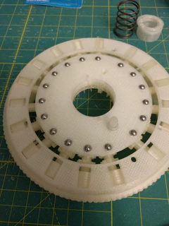
- The carriage with ball bearings ready for the spider spring. Note the carriage spring and associated parts above it.
- The carriage with the spider spring in place.
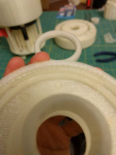
- Clearing ring with the clearing teeth installed.
- I printed those in much the same way as the Curta was made.
- They are created flat and then curved and pressed into the bottom of the clearing ring.
- They had a good bit of friction, but I ended up using super glue to keep them in place.
- The main part of the Curta with the collar added with M3 screws.
- I did have to widen the holes slightly for the heads of these screws.
- Close up of the top of the Curta fully assembled.
- Selector shafts on completed Curta.
- Reversing lever on completed Curta.
- Top view of completed Curta.

